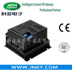
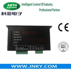
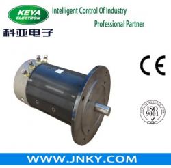
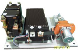
Dc Controller Assembly/high Current Dc Speed Contr
| Price : | $0.01 |
| Quantity : | 3000 (set) |
| Minimum Order : | 3 |
| Product Status : | New |
| Sample Available : | yes |
| Shipment Terms : | Negotiable |
| Payment Mode : |
T/T,L/C,cash,cheque |
| Categories : | Electrical & Electronics, Circuit Board |
| Posted By : | Jinan Keya Electron Science And Technology Co.,ltd |
Description
1.1 The controller assembly shall be installed in ventilated and dry place, near storage battery and motor, and away from rainwater.
1.2 The wires of pilot circuit and main circuit shall be properly connected according to the wiring diagram. First connect pilot circuit,
and then connect main circuit with controller after inspecting the wiring to ensure its correctness.
The sectional area of main circuit wire depends on the motor power and it is usually not less than 25mm2.
The sectional area of control circuit wire is not less than 1 mm2.
1.3 Use multimeter to measure the direct current voltage on the either end of the storage battery to ensure
its conformity with the required operating voltage for controller assembly.
1.4 Close key switch, and contactor pull-in sound shall be heard.
1.5 If the indicator light (green light) in the front of chopper is ON, it indicates normal conditions for the next step of debugging.
1.6 Lift up the vehicle to let the driving wheels off the ground.
1.7 Use remote control panel to individually control the forward or backward speed of the controller assembly.
2. Usage
2.1 Put down the lifted vehicle and let the driving wheels on the ground. Drive the vehicle according to the methods described in 1.7 and 1.8.
2.2 With the function of under-voltage protection, the controller assembly will
stop working when its input voltage is lower than the 80% of its operating voltage.
2.3 With the function of over-voltage protection, the controller assembly will
stop working when its input voltage is higher than the 120% of its operating voltage.
2.4 With the function of over-temperature protection, the controller assembly will
stop outputting when the chopper temperature is higher than 75 and
the controller assembly will automatically restore its current output
after the chopper temperature declines.
2.6 If the vehicle needs reversing during the running process, it shall be stopped before reversing.
3. Maintenance
Most of time, controller assembly needs no maintenance,
but it is recommended to perform the following cleaning and servicing when it is in use
3.1 Open key switch and pull the reversing switch to neutral position.
3.2 Connect a temporary load (such as a resistance of dozens of Ω and above 10W, a 110V or 220V bulb, etc. )
between the terminal B+ and B- of controller assembly, and then discharge the residual current in the capacitor of chopper.
3.3 Remove the dust and dirt on copper wire and clean each component with cloth (NOTE: Do not wash in water).
3.4 Use tool to fasten the nuts and bolts between the wire connector and copper raw.
Attention shall be paid to the force used in the operation to prevent from twisting or
transforming the copper raw.
4. Main Technical Parameters for Controller Assembly
| Applicable voltage range Chopper operating frequency Electric lock input voltage Electric lock input current Over-voltage protection Contactor driver operating voltage Contactor driver current Applicable ambient temperature for controller assembly Maximum allowable temperature for chopper Voltage range for acceleration signal input Voltage range for potentiometer signal input | ±20% of operating voltage 15KHZ same as system voltage 60mA (typical value), pre-charge about 350mA in 3 seconds after starting 120% of operating voltage same as controller operating voltage 2A(over-current protection 3A) -25~50 75 1~5V 0~5V |
 |
|